9 Ways To keep Your Rs485 Cable Rising With out Burning The Midnight O…
페이지 정보

본문

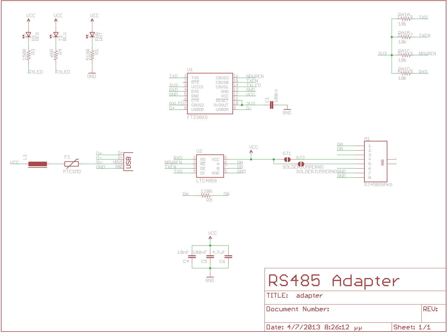
Note that the local and the remote must share a common ground, so a minimum of 5 wires are required for full duplex RS422 communications: two transmit wires, two receive wires, and a common ground. Chassis and signal grounds are connected together to the digital ground (GND) signal. To provide a convenient means of attaching two grounds to the serial cable, there are several pins (labeled GND) on the communications connector that are connected to the controller’s ground plane. In this case, cable connections must be made to Serial 1 at pins 5 and 6 of the 10-pin Serial Header or pins 7 and 8 on the 24-pin Field Header. There are surface mount resistor pads on the QScreen that will allow you to bring out the secondary serial port to the Field Header on pins 5-6 or 7-8 as shown with the parentheses in Table 11-3. Pads are also available to bring out the RS485 signals to the DB9 Serial 1 Connector. The protocols are described in turn. RS-485 is used as the physical layer underlying many standard and proprietary automation protocols used to implement industrial control systems, including the most common versions of Modbus and Profibus.
The dual communications channels also provide an easy way to link systems that communicate using different serial protocols. A jumper, J3, configures the primary serial port for either RS232 or RS485 operation. What made it such an advancement over RS232 was the fact that it could transmit not only a single device to device transmission, but also a communications bus to connect multiple devices at once. Because it may be used at high speeds, over long distances, in electrically loud settings, and with multiple devices on the same bus, RS-485 is a good choice for most serial interface applications. Thus RS485 is the standard protocol of choice when multi-drop communications are required. All communication cabling to be installed in a daisy chain configuration, no T’s are permitted. Just like it’s older brother RS232, RS485 is a form of serial communication. The QScreen Controller’s transmit data signal TxD1 (pin 2 on the 9-pin serial connector) is connected to the terminal’s receive data signal RxD (pin 2 on its 9-pin connector).
The SCK (serial clock) pin is a configurable synchronous data clock output. The serial data stream at the UART is conditioned by serial driver chips that transmit and receive the data. Each RS422 driver transmits a differential pair of output signals at 0 and 5 volts. The RS485 protocol uses differential data signals for improved noise immunity; thus RS485 can communicate over greater distances than RS232. A modem (modulator/demodulator) provides a way of encoding digital data as a set of audio signals that can be sent over a telephone line. We can gain insight into the operation of the RS232 protocol by examining the signal connections used for the primary serial port in Table 9 6. The transmit and receive data signals carry the messages being communicated between the QScreen Controller and the PC or terminal. Given the availability of ready-made communications cables, it is not necessary to study or understand the following descriptions of cable connections. The RS485 connections are not brought out to the Serial 1 Connector.
24 AWG solid wires, which are typically used in Cat 5 cables, can break easily when connected to a screw terminal block, which does not provide any strain relief. The RS232 protocol provides for four handshaking signals called ready to send (RTS), clear to send (CTS), data set ready (DSR), and data terminal ready (DTR) to coordinate the transfer of information. By connecting pairs of these handshaking signals together, the terminal or PC can be made to think that the QScreen Controller is always ready to send and receive data. The QScreen Controller does not differentiate between these. The default serial routines used by the onboard kernel assume that full duplex communications are available, so you cannot use the RS485 protocol to program the controller. These factors are discussed in more detail in The UART Wildcard: Modem Handshaking Signals. These signals may alternatively be redirected to the digital inputs and outputs used by the second serial port if hardware handshaking is required. The Serial 1 port is implemented with the 68HC11's on-chip hardware UART (Universal Asynchronous Receiver/Transmitter). The primary channel’s UART translates the bit-by-bit data on the serial cable into bytes of data that can be interpreted by the QED-Forth Kernel or by your application program.
If you liked this write-up and you would certainly such as to get more facts pertaining to rs485 cable kindly see the internet site.
- 이전글시알리스200mg,카톡-hpp9 24.07.05
- 다음글Buzzwords De-Buzzed: 10 Different Ways To Say Uk Online Shoe Shopping Websites 24.07.05
댓글목록
등록된 댓글이 없습니다.

