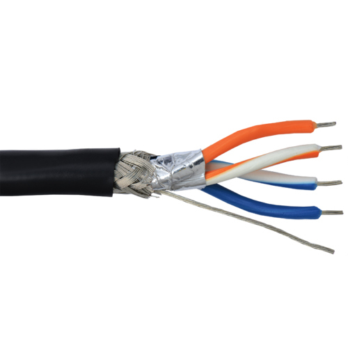
World Class Instruments Make Rs485 Cable Push Button Easy
페이지 정보

본문

Connecting computers together in multi-drop networks is common in factories and laboratories. The standard does not discuss cable shielding but makes some recommendations on preferred methods of interconnecting the signal reference common and equipment case grounds. For the QScreen, /SS is not used for SPI communication because it is used to control the direction of the RS485 transceiver; you can use any digital I/O line as a /SS signal. This section describes the QED-Forth routines that control the RS485 transceiver, and presents some ideas that may prove useful in designing a multi-drop data exchange protocol. The master and slave could even exchange ascii QED-Forth commands. QED-Forth includes three built-in routines to facilitate control of the RS485 transceiver. If more than one slave tried to drive the transmit line simultaneously, their serial drivers would fight with each other for control of the bus. At any given time, only the master and a single "active" slave communicate. The InitSPI() function provides a convenient way to initialize the SPI as the master at a 2MHz baud rate. In general, all devices on a network should use the same phase, polarity, and baud rate clock signal. Note that the master device outputs the clock synchronization signal SCK to the slave’s SCK which is configured as an input.
As the master transmits its data, 8 bits of data are simultaneously received. Although data byte transfers are easily executed once the network has been wired and configured properly, a carefully executed software protocol may be required to ensure data integrity. It may be that only the byte sent from the master to the slave is meaningful; nevertheless, each device simultaneously transmits and receives one byte. The GROUND line serves as a common voltage reference for the master and slave. In the most common multi-drop RS-485 protocol, one computer is designated as a "master" and the rest of the computers or devices on the serial bus are designated as "slaves". Transmissions are always initiated by the master device, and consist of an exchange of bytes. When the /SS input goes low, the slave (or QScreen in this case) transfers data in response to the SCK clock input that is initiated by the master. A data transfer is initiated by a master device when it stores a message byte into its SPDR register. If the /SS pin of the master is an input and if a low input level is detected, the processor sets the MODF bit in the SPI status register a "mode fault" condition.
RS485Receive() clears bit PD5 to place the transceiver in receive mode, and RS485Transmit() sets bit PD5 to place the transceiver in transmit mode. SPIE is a local interrupt mask that allows an interrupt to be recognized when an SPI data transfer has completed, or if a write collision or mode fault is detected. This is great for Supervisory Control and Data Acquisition (SCADA) systems where there are many devices and it also comes at a very low cost to implement. As the master transmits a byte to an active slave (that is, a slave with its /SS input active low), the master receives a byte from the slave. The /SS (active-low slave select) is typically used to enable data transfers by slave devices when it is active low. The status of a device as master or slave determines how the various pins must be configured. This detects the presence of more than one master on the SPI bus. To use a QScreen as a slave in a multi-drop network, simply define a word, (named Silence(void), for example) that when executed calls RS485Receive() to wait for any pending character transmission to complete, then disable the transmitter, and then execute a routine such as Key() to listen to the communications on the serial bus.
It is like the Universal Serial Bus (USB) or ethernet that we can find in many of our modern computers. 2. USB Cable 1m. & Driver CDROM. Although the maximum standard baud rate of the primary serial port is 19200 baud, nonstandard baud rates of over 80 Kbaud can be attained by the 68HC11's on-chip UART and the onboard RS232 driver. The maximum sustainable baud rate on the secondary serial port is 4800 baud. You might also consider operating the secondary serial port at a lower baud rate to relax the timing constraints. The rate of data transmission is expressed in bits per second, rs485 cable or baud. The SPI can transfer data much more rapidly than an asynchronous serial link - its maximum rate is 2 Megabits/second. You can find out more about the differences between RS485 and RS232 here. If you’re very sure that you are only using RS485 then you will not be disappointed with the former.
- 이전글9 Strategies Of Uk Lunch Time Result Domination 24.06.10
- 다음글The 10 Scariest Things About Online Shopping Top 7 24.06.10
댓글목록
등록된 댓글이 없습니다.

