7 Stories You Didnt Know About RS485 Standard
페이지 정보

본문
When the driver increases the voltage on one of the wires, it simultaneously decreases the voltage on the other wire resulting in a differential voltage between the two wires. RS-485 simply defines the interface connection points as "A" and "B" and shows the voltage relationship between "A" and "B" for the binary states of the two wires, not the binary state of the input to the driver. I've been told that 10BASE-T Ethernet and SCSI cables use a bunch of RS-485 pairs -- is that right ? Many other IC manufacturers make a drop-in replacement for this IC, and many of them (such as the MAX483) use the same labeling. A decent oscilloscope that is isolated from earth ground (battery operated or powered by an unplugged UPS (if you're good enough with a scope you can also subtract channel 1 from channel 2 to see the differential waveform, or use a differential probe, etc.)) can be a very useful troubleshooting tool. EIA-485, also known as TIA/EIA-485 or RS-485, is a standard defining the electrical characteristics of drivers and receivers for use in balanced digital multipoint systems. Using RS-485, it is possible to construct a multi-point data communications network. The RS485 standard is used when high speed serial data communications of 10 Mbps is needed.
The RS-232 standard title is "Interface Between Data Terminal Equipment and Data Circuit Terminating Equipment Employing Serial Binary Data Interchange". When used as a converter, the master RS232 port provides bi-directional serial conversion to the 8 RS485 distribution ports. RS485 is able to provide a headline data rate of 10 Mbps at distances up to 50 feet, but distances can be extended to 4000 feet with a lower speed of 100 kbps. The RS485 drivers allow 32 standard loads at 4000 ft. The standard is defined by industry telecommunications bodies and may be referred to most commonly as RS485, but references to EIA485 or TIA-485 may also be seen. However, you may find situations where you need to connect the interface to external hardware that is prewired with a common ground and what you need to do is switch the hot, or power side, of the loads. Edge mounted LEDs display power and master port(s) data activity. User connections are compression screw terminal strips for the RS485 ports, an RJ11/12 telephone style connector for the RS232 port, and a 2.1mm barrel connector or 2 pin terminal strip for supply power.
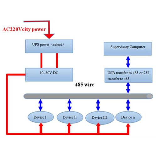
A polarity protected efficient switching regulator accepts supply voltages from 9 to 35VDC, at 0.5 Watts max. For these microcontrollers, the Linux driver should be made capable of working in both modes, and proper ioctls (see later) should be made available at user-level to allow switching from one mode to the other, and vice versa. RS485 communications. This data structure is used to set and configure RS485 parameters in the platform data and in ioctls. TIOCSRS485 and TIOCGRS485 ioctls (see below). The first is that if the line is long enough, an AC "ohmmeter" connected to the input of the model will see the "resistance" of the wires as 120 Ω. Half of the conductors in a 50 way cable are ground return wires. In a typical applications several address able devices may be linked to a single controlled (PC), and in this way a single line may be used for communication. This is a rather convoluted way of saying pin 7 of the DB-25 connector is used as a signal common.
The standard defines the common-mode voltage as being referenced to ground, it defines a term "ground potential difference" as the difference in the signal ground between the driver and receiver, but it does not say that this is earth ground or just a a third wire common. Alternatively, with current-sourcing the SMINI provides the actual voltage that activates the railroad device. If more than one segment happens to be turned on, the software within the SMINI defaults to using the baud rate corresponding to the highest switch segment with an "on" setting. For an on, space or logic 0 state, the driver's A terminal is positive relative to the B terminal. A logic device may have an "inverting" and/or "non-inverting" output. The standard does not define the logic function of the driver or receiver. The foreword to the standard references The Telecommunications Systems Bulletin TSB-89 which contains application guidelines, including data signaling rate vs. When the computer is to read data from the SMINI input ports, it simply tells the PIC16F877, which gathers the data from the 3 input ports, sets it up in the prescribed format, and transmits it bit-by-bit back to the computer.
- 이전글Six Tendencies Shaping The future of The worldwide Construction Industry 24.05.20
- 다음글씨알리스 부작용-타다라필 지속시간-【pom555.kr】-비아그라 증상-《카톡CBBC》 24.05.20
댓글목록
등록된 댓글이 없습니다.