>>>2024-06-02 Consumer Electronics Control (PDF)
페이지 정보

본문
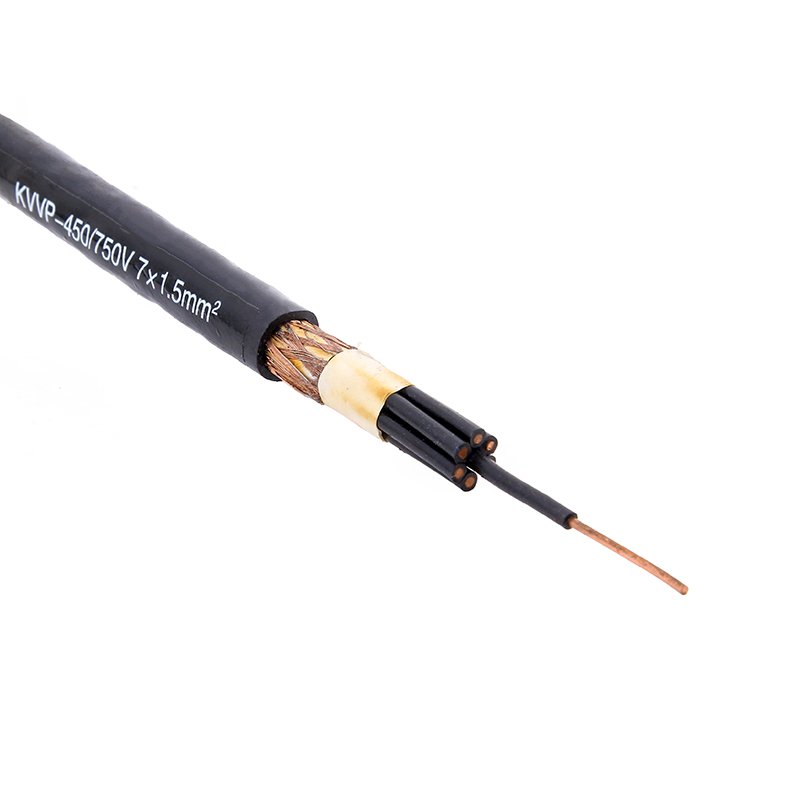
 Note: I realize that the data on this web page may be complicated and tough to comply with. Unfortunately, actual circuit boards have exterior cables hooked up, and one of the cable could attach the circuit floor to an exterior ground, shield control cable probably an Earth floor. Create a seperate I/O area and that i/O floor aircraft on the circuit board, permitting the chassis-to-circuit floor connection to be made with minimal common-mode present circulation. 490's connection plug, this meant that the camera's exposure system would nonetheless be set for normal current gentle images. Thus, USB shield connection seems to be a moderately "polarized" drawback: if you are doing it incorrect, you'd better to do it improper all the way in which. Does it matter if the shield will get shorted to floor on the host facet versus the system facet? Because the shield is already related to the chassis, the problem of whether the shield needs to be related to the circuit floor can also be implied right here.
Chassis floor is any conductor that is linked to the equipment’s steel enclosure. Higher frequency signals (21-28 MHz) have a shorter wavelength and want a couple of sq. meters (tens of sq. feet) of metal surface situated near the tuner. Test images have been taken at a distance of 5 feet, which was chosen on account of it being a typical distance for indoor portraits, and likewise with the intention to accomodate the Kako Mite's mounted flash output (with ASA 80 film and the cameras' f/8.8 lenses, optimum publicity needs to be at something around 5 feet). This flash has a guide variety of one hundred ten (ASA 100, distance measured in feet). This picture also turned out perfectly exposed (primarily an identical to the opposite image taken with this flash), however, as expected, this time the shutter closed after the flash fired (as it should). This photograph turned out to be significantly overexposed, with fantastic particulars almost fully washed out. For high-pace RF and digital systems, that is normally thought-about to be an appropriate price - practical RF shielding is much more important than a few millivolts of negligible noise, which is below the logic threshold or may be filtered out. So, to make a protracted story short, I've now carried out just a few somewhat controlled experiments with electronic flash on 'traditional' Polaroid automated pack cameras.

So, I'm leaving that out for now. So, for the next check, I re-related the Rollei flash using the 'regular' Pc cable, but set the flash to full-power (handbook mode). One is a excessive-energy (but not notably modern) thyristor computerized shoe-mount flash, a Rollei 134 REB. The third take a look at photograph was made utilizing the Kako Mite, and this one turned out slightly underexposed, but better than with the 450. As with the Rollei flash, the shutter closed immediately after/throughout the firing of the flash. The fourth check was with the Rollei flash and my 'special' cable as described earlier. Next, I hooked up the Rollei digital flash. I used the Kako Mite digital flash for the third take a look at. Because of the encouraging results in the 2nd and third assessments, I made two further take a look at pictures to find out if the metering system was truly ready to respond during the temporary flash duration of those digital flashes. Since there are literally hundreds of different fashions of flashes out there made by dozens (if not hundreds) of different manufacturers, there isn't any method for me to know whether or not or not your explicit flash/digicam combination will work to your satisfaction. Two very totally different digital flashes were selected for this experiment.
Each of the 2K characters was represented by two bytes: a character byte, and an attribute byte. The potential difference across the 2 conductors create a noise present circulate throughout your complete cable's size, creating frequent-mode radiation. The computerized radiation doze control system on the nuclear power plants with reactors of the RBMK-1500 sort is provided with amenities monitoring radiation publicity of all elements and systems of the station. The RBMK-1500 reactor is supplied with particular elements and systems ensuring radiation safety of the nuclear energy plant and the surroundings both under normal operating conditions and within the emergency circumstances. The health physics laboratory is provided with amenities and sampling strategies, dozimetric, radiometric, spectrometric instruments for objective assessment of the radiation circumstances in the environment. To cut back radioactive aerosol emissions on the nuclear power plants with the RBMK-1500 reactors provision is made for purification facilities absorbing aerosols by special filters. The info logging system is configured in a 3-stage hierarchy using computers SM-1M and SM-2M and interface amenities.
- 이전글9 . What Your Parents Teach You About Car Keys Repair 24.12.17
- 다음글비아그라커피-시알리스 20mg-【pom555.kr】-비아그라탄생 24.12.17
댓글목록
등록된 댓글이 없습니다.

